2. At spray volume fluxes above 2.0×10⁻³ m3/(m2.s), a reduction in
gravity causes an increase in the CHF (critical heat flux).
3. Optical observations of the heater surface from its rear side revealed
that droplets fed onto the surface at lower spray volume fluxes completely
vaporized there, without showing mutual interactions, as long as the surface
temperature is close to the CHF-point temperature.
For CFC-113 and FC-72:
1. At spray volume fluxes above 5.0×10⁻⁴ m3/(m2.s), a reduction in gravity
yields an increase in the CHF.
2. According to the observations of heater surface held at, or close to,
the CHF point, droplets integrate into quite thin liquid films, which are
immediately swept away.
The above results indicate some gravity dependency of the spray-cooling
heat transfer, which is qualitatively consistent with the results of the
previous terrestrial spray-cooling experiments on the influence of the
heater-surface orientation(4). However, following issues are still left
to be clarified.
1. the variation of gravity dependency of spray-cooling heat transfer with
a variation of spray volume flux,
2. the variation in gravity dependency with a variation of chemical species
of spray-forming liquids, and
3. effects of gravity on the behavior of droplets and liquid films on the
heater surface.
Another series of parabolic-flight experiments was planned with an
intention to clarify the above-listed issues, and it was performed in November
1996, again using the MU-300 aircraft.
EXPERIMENTAL
Apparatus
The apparatus constructed in the authors* previous studies(1-3) were
used as it was except for the selection of spraying nozzles. Although the
details of the apparatus have already been reported(1-3), a brief description
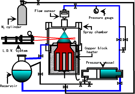
of the apparatus is given below for readers* convenience. Figure 1 schematically
illustrates the assembly of the apparatus. The liquid in a pressure vessel
was displaced by pressurized dry nitrogen gas so that the liquid was sprayed
from a nozzle into a spray chamber. The liquid thus sprayed onto the surface
of an electrically-heated copper block installed in the chamber vaporized
completely or partly. The vapor filling the chamber and, if any, a residual
liquid were then discharged into an external reservoir to be stored there.

Fig. 1 Experimental Apparatus
|
|
Three different full-corn nozzles (Unijet type TG, Spraying Systems
Co., Ltd. ) were used alternately to spray water or FC-72, a perfluorocarbon
fluid, onto the heater surface in the chamber filled with nitrogen gas
nearly held at the normal atmospheric pressure. The spray volume flux could
be changed by exchanging the nozzle in use for another. Any nozzle put
to use was so fixed at a position 100 mm above the heater surface that
it was pointed at the center of the surface.
An LDV (Laser Doppler Velocimeter) with a 15-mW He-Ne laser and a frequency
shifter was also took on board to measure, through a side window of the
spray chamber, the velocities of droplets impinging upon, and rebounding
from, the heater surface. The measuring point was 25 mm away from the heater
surface along the common axis of the heater and the spray.
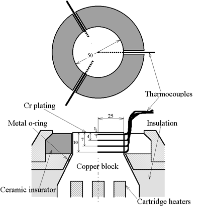
Figure 2 illustrates the structure of the upper portion of the copper
block used as the heater. The positions of twelve 0.25-mm diameter sheathed
chromel-alumel thermocouples inserted into the block are indicated. Before
each experiment, the copper block was heated up to a prescribed temperature
(up to 400℃) by seven 1-kW cartridge heaters embedded in the block from
its bottom. The block was then cooled down transiently by spraying a liquid
onto its surface. The junctions of those thermocouples were fixed at four
different depths from the top surface of the block and at three different
radial locations: i.e., just on the axis of the block, and 8 and 15 mm
offset from the axis. Each thermocouple was stuck into a 0.35-mm dia. holes
with a thermal-resistant alumina-silica adhesive. The cooling of the block
was monitored simultaneously with the twelve thermocouples. The surface
heat flux and the surface temperature at each instant were calculated from
the instantaneous temperature distribution inside the block detected by
those thermocouples.

Fig. 2 Structure of Copper Block Heater
(Reproduced from Oka et al.(2))
|